HELICIEL automatically optimizes profiles by selecting their according to lift / drag ratio and maximum thickness distribution. These two qualities are antagonistic they involve a compromise between strength and performance of our wing or propeller blade. The main qualities for which a profile is selected is its lift / drag ratio and strength provided by its thickness. The performance of our system is an implacable judge of our work! The optimum performance will be obtained only if we properly design our profiles propeller blade or wing. Whether in terms of finance or quality workmanship, materials and efforts for the realization of a project need to be offset by the quality of the result. Optimize the shape of the profiles A system with a propeller or wing can have a more or less efficient. In Heliciel, performance of calculated or measured profiles are stored as database containing the CL (lift coefficient), Cd (drag coefficient), Cm (moment coefficient) relative to each angle of incidence, and each reynolds number, in which the profile was evaluated and normalized coordinates defining the geometrically. The interactive data base héliciel has a profile editor naca 4 digits that allows you to generate airfoils and transform at will for more information: interactive data base héliciel:

The predecessor of NASA was the NACA (National Advisory Committee for Aeronautics).
#Airfoil blade download#
To use it simply download on the interactive data base page héliciel
#Airfoil blade free#
Heliciel provides free database of profiles with their polar of about 1,000 profiles of all kinds. Of these, profiles NACA type are well known, and in some commonly used as practice for the validation of numerical methods. Note, for example, Joukowski, Eppler, Wortmann, NACA, RAE, Göttingen, NLR, NASA / LRC and SANDIA profiles.

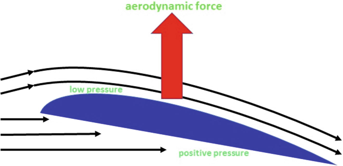
We denote by f the greatest ordinate of the mean camber line over AB.The mid-perpendicular to the reference chord segments, such MN is called the profile or skeleton mean camber line.APB = camber line profile compared to the speed of the flow, Vinfini.d = the maximum position of the profile camber.a = angle attack (or geometric incidence ).D = drag force paralelle resistant to fluid displacement expressed in newtons.L = lift force perpendicular to the displacement of the fluid expressed in newtons.The shape of the profile is an essential feature of a wing and greatly affects the aerodynamic characteristics and performance of an aircraft.Īccording to the figure above, we define the following geometric quantities of an airfoil

One defines an airfoil as the geometric shape that is obtained by the vertical section of an airplane wing.

between the tube and the sheet we have the airfoil. Make it fly a tube is fairly complicated (although this is possible by rotating it but we'll talk about later), and to collect the necessary thrust to propel a boat with a sheet of paper is quite complicated too. įrom the point of view of mechanical strength to the best performing weight / resistance is the tube. A slight bend for lift and our sheet s' flies away effortlessly. In the aerodynamic or hydrodynamic point of view, the higher the profile is fine unless it generates a resistance to the advancement. The compromise between performance and mechanical strength is at the heart of the problem of the definition and optimization of the geometry of the wing or blade. The profile shape of the wings or blades determine their aerodynamic or hydrodynamic performance but also their mechanical strength.


 0 kommentar(er)
